Homography - Stereo
Homography
Given the same object and two images taken from different worlds. WTF the transformation from one to another.
3D relationship
Let the object be a plane (say a book). Then we can characterize the plane by one point \(d\) and two independent vectors \(a,b\) on the plane, i.e. we create a coordinate system with an origin and two basis. Therefore, we can describe any point \(X\) on the plane by \(X = d + \alpha a + \beta b\).
Let \(X_1 = d_1 + \alpha a_1 + \beta b_1, X_2 = d_2 + \alpha a_2 + \beta b_2\) where \(X_1, X_2\) represents the two planes in 3D of the two world, and represents the same location relative to the same object plane.
Using homogeneous coordinates
And the transformation \(T\) between them gives \(X_2 = T X_1\), i.e. \(A_2\begin{bmatrix} \alpha\\\beta\\1 \end{bmatrix} = TA_1\begin{bmatrix} \alpha\\\beta\\1 \end{bmatrix}, \forall \alpha, \beta\). Therefore, \(T = A_2A_1^{-1}\)
2D relationship
Consider the projective (image) plane. Let \(K_1,K_2\) denotes the different intrinsic parameters. Then \(w_1\begin{bmatrix}x_1\\y_1\\1 \end{bmatrix} = K_1X_1, w_2\begin{bmatrix}x_2\\y_2\\1 \end{bmatrix} = K_2X_2\), known that \(X_2 = TX_1\), so that
Note that \(K_2TK_1^{-1}\) is a \(3\times 3\) matrix. Therefore, without knowing all the 3D location and even the camera parameters, we can still do the transformation by finding \(K_2TK_1^{-1}\) as only one matrix
Rotating the camera
Consider the panorama mode of the camera. Assuming of the rotation of the camera happens.
Let \(R\) be the rotation of the camera, then \(R^T\) is the rotation of the 3D points. Let \(X_1,X_2\) be the same point of the object in the two camera coordinates. Then, let \(T:= R^T\), i.e. the transformation is a rotation, then
Moving the camera
Let the movement be \(t\), then \(X_2 = X_1 -t\), so that in the homogeneous coordinate of the 2D image
However, changing \(w_1\) will give different points in the second image.
On the opposite, if we have \((x_1,y_1), (x_2,y_2), K, t\), we can calculate \(w_1, w_2\), hence compute the point in 3D.
This fact is called stereo.
Stereo
A 2D image cannot represent the depth in 3D world, i.e. \(Z\)-axis is dropped. However, using stereo cameras we can reconstruct depth.
Parallel stereo Cameras
Let \(O_t,O_r\) be two camera centers, \(O_r = O_t + [T, 0, 0]^T\), i.e. We apply a movement \(t\) to the left camera along the \(x\)-axis to get our right camera.
Consider \(p_l = (x_l, y_l), p_r = (x_r,y_r)\) be the projected points of \(Q\) on left, right image plane, respectively.
Since we only move the camera along the x-axis, \((p_l\sim p_r) \parallel (O_l\sim O_r)\), hence \(y:= y_l = y_r\).
Also, noticing that we are only interested in \(Z\), i.e. the depth. Consider the connection between \(p_l, p_r, Z\), ignoring \(y\) since it is unchanged. Therefore, we can project the image from the y-axis, and see the relationship in 2D \((x,z)\) coordinate.
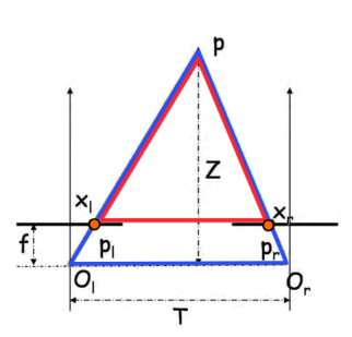
Noticing that \(\Delta PX_lX_r \sim \Delta PP_lO_r\). so that
Then, to get \(x_r\), we need to match the point in two images. Since we know \(y\) of the point is constant, we can do a sliding window scan along the same \(y\), then patch around \(x_r\) to get the highest similarity.
General Stereo Cameras
Basic Setting
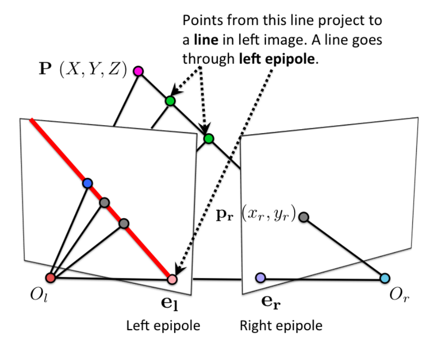
Epipole \(e_l, e_r\) where line \(O_l, O_r\) intersects the image planes
Projective line \(O_lp_l, O_rp_r\) will project to the right, left image plane. Note that the line will not (necessarily) be horizontal.
Epipolar plane the triangular 2D plane in 3D space that it formed by \(O_lO_rP\), where \(P\) is an arbitrary point in the camera's view point.
Epipolar line the intersection between the epipolar plane and the image plane. However, all epipolar line will intersection at \(e_l, e_r\)
Given \(p_l\) in the left image plane, we are able to compute the epipolar plane passing through \(p_l\) and hence the correspondent epilolar line in right image, hence search \(p_r\) on a line.
Cross Product
For two \(3\times 1\) vectors \(u,v\), the cross product is defined as
Note that \(u\times u =0\) and \(u\parallel v \Leftrightarrow u\times v = 0\)
Geometrically, the cross product defines the line perpendicular to both \(u,v\), i.e. \(u\cdot(u\times v) = v\cdot(u\times v) = 0\).
Essential Matrix E
maps 3D points from the frame of one camera to the frame of another camera.
Consider \(X_l, X_r\) be the same 3D point in left, right camera frames. Because we are changing the perspective on the same point, we are get the transformation by a translation and a rotation
Fundamental Matrix F
Let \(I_r\) be the epipolar line corresponding to \(p_l\), the fundamental matrix \(I_r= Fp_l\). Note that for any \(p_l\), \(F\) is unchanged.
Note that for any point \(P\), its projection on the 2D image frame is \(p = K[R\mid t]P\) (projection matrix)
Since both 3D points on the image frame are the identical 3D point in the world. Let \(X_l = [R_l\mid t_l]P, X_r = [R_r\mid t_r]P\), assuming using the same camera, i.e. the same \(K\). Therefore, \(p_l = KX_l, p_r = KX_r\Rightarrow X_l = K^{-1}p_l, X_r = K^{-1}p_r\)
Therefore, \((K^{-1}p_l)^T E K^{-1}p_r = 0\), then \(p_l^T(K^{-1})^TEK^{-1}p_r = 0\Rightarrow p_l^TFp_r = 0\), where \(F:= (K^{-1})^TEK^{-1}\)
Noting that \(p_l^TFp_r = 0\Leftrightarrow p_l^T100Fp_r = 0\), i.e. \(F\) is scale independent, also note that \(E\) is rank 2, hence \(F\) is rank 2. \(\Rightarrow \det F = 0\). Therefore, degree of freedom is \(9-1-1=7\)
Computing F (8 Point matching algorithm)
Consider \(8\) matching points, \(p_{l1}, p_{r1},...,p_{l8}, p_{r8}\). Then, we have 8 equations \(p_{li}Fp_{lr} = 0\). We can flatten \(F\rightarrow \vec f\) and write the equations as vector products \(a_i\vec f = 0\). Then, we can form system of equations
Note that \(\vec f\) is the null space of \(A\). Using SVD, \(A = UDV^T\), and set \(\vec f\) to the column of \(V\) corresponds to the smallest singular value in \(D\), and reshape \(\vec f\) to \(F\).
Then, we can impose \(\det F= 0\) constraint by SVD on \(F = UDV^T, D= diag(d_1,d_2,d_3)\) where \(d_1>d_2>d_3\), then we can set \(d_3=0\), i.e. \(\hat D = diag(d_1,d_2,0)\) and let output \(\hat F = U\hat DV^T\)
Computing epipolar lines
Note that \(F\) is scale invariant, hence \(p_l^TFp_r = 0\Rightarrow l_l = Fp_r\) is the epipolar line on the left image.
Similarly, \(p_l^TFp_r = 0\Rightarrow (p_l^TFp_r)^T = 0\Rightarrow p_r^TF^Tp_l = 0\Rightarrow l_r = F^Tp_l\) is the eipolar line on the right image.
Computing epipoles
Wlog, using the left image.
Note that all epipolar lines \(l_l\) intersect at \(e_l\), hence \(e_l^Tl_l = e_l^TF^Tp_l = 0\), take \(p_l=1\), then we solve \(e_l^TF^T = 0\), and \(e_l=\) vector that is null space of \(F\) (rank 2).
Rectification Matrix
If \(F\) is knowing, we can compute the relative poses of the two cameras.
Setting \(P_l = [I_{3\times 3}\mid 0]\) be the reference camera, \(P_r = [[e_r]_xF\mid e_r]\), then \(P_r\) is the rectified projection matrix.